Power supply
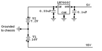
The power supply consists of two batteries: a 16V LiPo pack to power the motors and a 7.2V NiMH to power the Arduino and logic circuits. A voltage regulator brings the logic voltage down to 5V.
Driving system
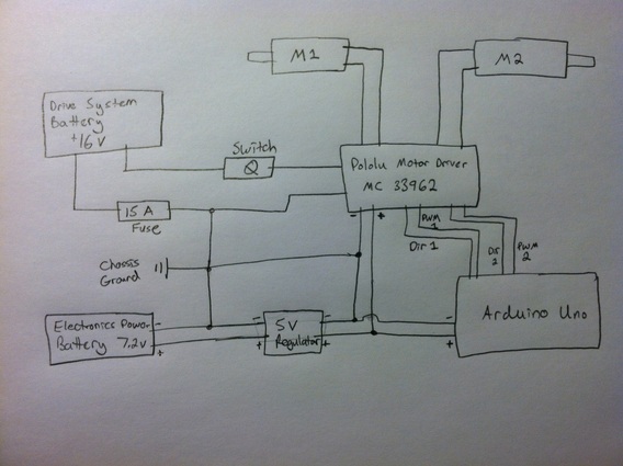
The motors M1 and M2 are driven by the Pololu Motor Driver, which is controlled by the Arduino Uno, and powered by the 5V regulator (LM7805C).
We used a +16V battery to power the motors without any voltage regulation (on purpose). And we made sure to connect together the grounds of the different power supply devices, and the chassis of the robot.
As recommended, we also used a switch and a 15A fuse.
We used a +16V battery to power the motors without any voltage regulation (on purpose). And we made sure to connect together the grounds of the different power supply devices, and the chassis of the robot.
As recommended, we also used a switch and a 15A fuse.
Arduino Uno pinout
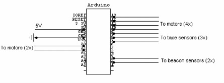
The Arduino was powered with 5V through the Vin. Five digital inputs were used to sense events through the three tape sensors and two beacon sensors. Four digital outputs allowed to control the speeds and directions of both motors. Two analog inputs allowed sensing of the motor current as an indicator of motor stall.
850Hz IR signal detection and circuit conditioning
IR Beacon
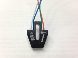
Each robot incorporated a mounting platform on top of the structure on which an IR beacon (like the one on the picture) was attached during a battle. This IR beacon modulated an infrared light at 850Hz that we could detect with our circuits.
The difficulty to detect the opponent was threefold:
1) another beacon was attached on top of the wall (called the Sequester) and modulated a signal at 4kHz that had to be filtered;
2) the IR noise coming from the environment also had to be filtered (DC signal);
3) we needed an efficient way to detect the opponent without adding too much complexity.
Strategy
So we decided to use two phototransistors pointing forward, but diverging a little from each other in order to widen the vision of the robot, and to enable us to know where to turn to face the opponent.
So we decided to use two phototransistors pointing forward, but diverging a little from each other in order to widen the vision of the robot, and to enable us to know where to turn to face the opponent.
Global circuit used for each of the 2 phototransistors
(output on the left connected to pin 2 or 3 of the Arduino)
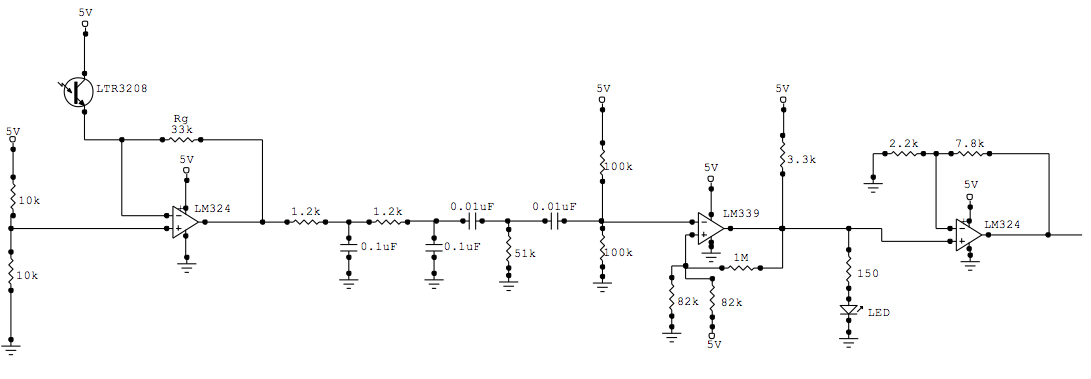
Trans-resistive circuit
Trans-Resistive Circuit
The 1st part of the circuit was a trans-resistive circuit in order to have a fixed voltage drop of 2.5V across the phototransistor.
We used a gain resistor of Rg=33k in order to have a signal strong enough for detection when the robot and the beacon are located at opposite sides of the platform.
The 1st part of the circuit was a trans-resistive circuit in order to have a fixed voltage drop of 2.5V across the phototransistor.
We used a gain resistor of Rg=33k in order to have a signal strong enough for detection when the robot and the beacon are located at opposite sides of the platform.
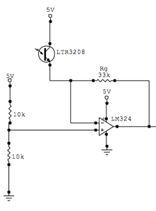
Filters
Filters
We added two 1st order low-pass filters giving a cut frequency of fc=1.3kHz, in order to filter the signal at 4kHz.
Plus two 1st order high-pass filters giving fc=300Hz, to filter the DC signal that we may have from the environment.
We also had to use a DC-offset because the mean value of the signal was cut down to 0.
Schmidt trigger comparator
Conversion Analog/Digital
The output signal of the circuit had to be analog because we needed to use the function "Interrupt" in the Arduino code to make sure that we would only react to the 850Hz signal. And this function could only be used on the digital pins 2 and 3 of the Arduino.
So we used a Schmidt Trigger comparator centered at 2.5V (voltage of the DC offset), with a width of 200mV.
In addition, we added a RED Led at the end of each of the 2 circuits that was on only when a robot was detected by the phototransistor. It helped us a lot during our tests.
Amplifying circuit
Non-inverting Amplifying Circuit
We also noticed that we needed to amplify the output of the comparator because the voltage was still too low for the high state input voltage Vih of the Arduino (probably because of the LED).
The amplitude was amplified approximately 4.5 times here, which guaranteed us that the output would saturate at 5V when the robot would be detected.
The output of the circuit is connected to either the digital input 2 or 3 of the Arduino.
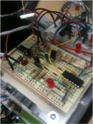
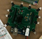
Breadboard with the two circuits for the two sensors
Line Detection
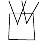
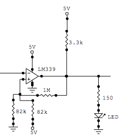
The playing field of our robot was a 4' x 8' white laminate table. The area in which it was allowed to roam was constrained by four strips of 1-in. thick, non-reflective black tape that formed a rectangle 6.5-in from the edge of the white laminate . To ensure that the robot would not travel outside of the allowed area, we developed a system that could detect the change in color of the playing field ground (white to black), and commanded the robot to move away from the black and towards the white. We implement the OPB704WZ reflective object sensor to accomplish this.
The OPB704WZ (left) consists of an infrared LED and a NPN silicon phototransistor that are mounted side-by-side. For the robot's purposes, the infrared LED shined light onto the ground and the phototransistor detected the amount of reflected light. The output voltage (Vout) of the phototransistor is directly proportional to the amount of light detected by the phototransistor. Thus, Vout is greater when the OPB704WZ is over the white laminate surface than when it is over the non-reflective black tape. When the OPB704WZ crosses the black tape from the white surface, a significant drop in Vout occurs. Using Arduino, we created a program to detect this change in Vout and react by retreating from the line.
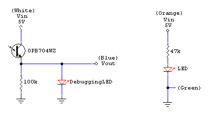
Left: Diagram of the OPB704WZ phototransistor circuit.
Right: Diagram of the OPB704WZ LED circuit.
(White, Blue, Orange, and Green refer to the colored wire of the OPB704WZ)
We implemented a 47kOhm resistor in the circuit of the OPB704WZ LED to remain within the current limitations of the hardware.
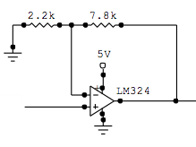
Using the resistance of the OPB704WZ phototransistor and a 100kOhm resistor, we created a voltage divider that allowed us to achieve a significant reading of the output voltage. A "debugging" LED was placed in the circuit using the Vout and ground to create a current. The debugging LED would light when a substantial Vout was detected (OPB704WZ over a white surface). If the OPB704WZ was placed over black tape, the debugging LED would not light. This would be very useful for testing. However, the debugging LED drew more voltage from the Vout line than we expected in order to light up. This created unexpectedly low Vout readings in the Arduino. To resolve this issue, we implemented a unity gain buffer (LM324) to isolate the debugging LED current from the phototransistor current without modifying the Vout of the phototransistor (see below).
Using the resistance of the OPB704WZ phototransistor and a 100kOhm resistor, we created a voltage divider that allowed us to achieve a significant reading of the output voltage. A "debugging" LED was placed in the circuit using the Vout and ground to create a current. The debugging LED would light when a substantial Vout was detected (OPB704WZ over a white surface). If the OPB704WZ was placed over black tape, the debugging LED would not light. This would be very useful for testing. However, the debugging LED drew more voltage from the Vout line than we expected in order to light up. This created unexpectedly low Vout readings in the Arduino. To resolve this issue, we implemented a unity gain buffer (LM324) to isolate the debugging LED current from the phototransistor current without modifying the Vout of the phototransistor (see below).
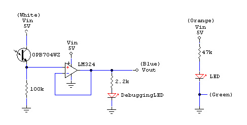
Left: Diagram of the OPB704WZ phototransistor circuit with unity gain buffer. This allowed us to isolate the debugging LED current from the phototransistor current.
Right: Diagram of the OPB704WZ LED circuit.
(White, Blue, Orange, and Green refer to the colored wire of the OPB704WZ)
