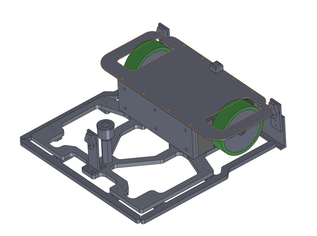
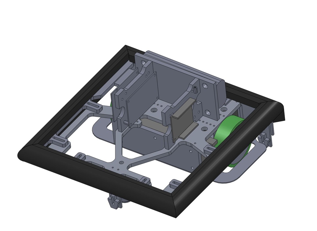
Strong Back Design
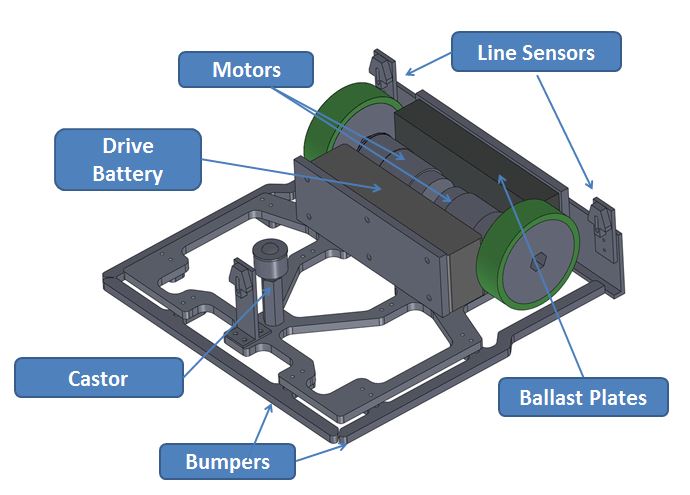
The starting point for the mechanical design was a single piece plate that formed the foundation for the rest of the vehicle.
This single piece plate, shown on the left provided the attachment features for the motors, batteries, ballast plates, block, line sensors and castor.
This "strong back" was a CNC cut aluminum part with 6-32 holes tapped in it for mounting the above mentioned components.
Material was removed from the side where the castor was located to help maintain the CG over the wheels of the vehicle. This was an important design feature for our vehicle and was intended to maximize traction, and make it difficult for opponents to push us off the table - which was demonstrated to be extremely effective in the competition where even more powerful opponents were only able to push our bot in circles.
Skid Plate
A skip plate bolted onto the bottom of the vehicle to protect our motors and batteries in the event that we departed the table.
Mounted to the far right of the skid plate is a skid pad. This pad was made of hard plastic, and was designed to keep the bot from pitching over when we changed directions suddenly in play. This feature was necessary because of the location of our CG directly over our wheels. Early in the development we found that without this critical parts like tended to shift on the vehicle due to repeated slamming of the castor into the table every time we changed directions.
Mounted to the far right of the skid plate is a skid pad. This pad was made of hard plastic, and was designed to keep the bot from pitching over when we changed directions suddenly in play. This feature was necessary because of the location of our CG directly over our wheels. Early in the development we found that without this critical parts like tended to shift on the vehicle due to repeated slamming of the castor into the table every time we changed directions.
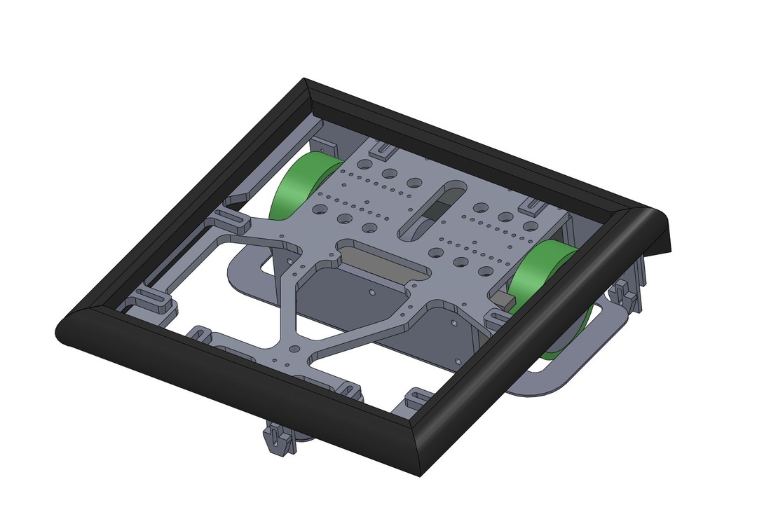
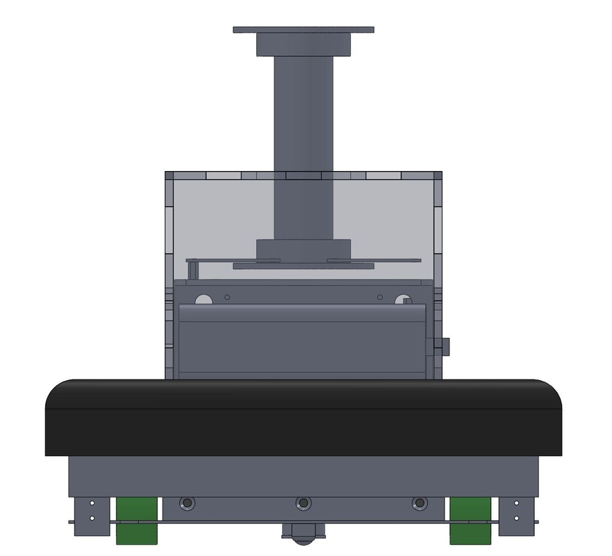
Adjustable Bumpers
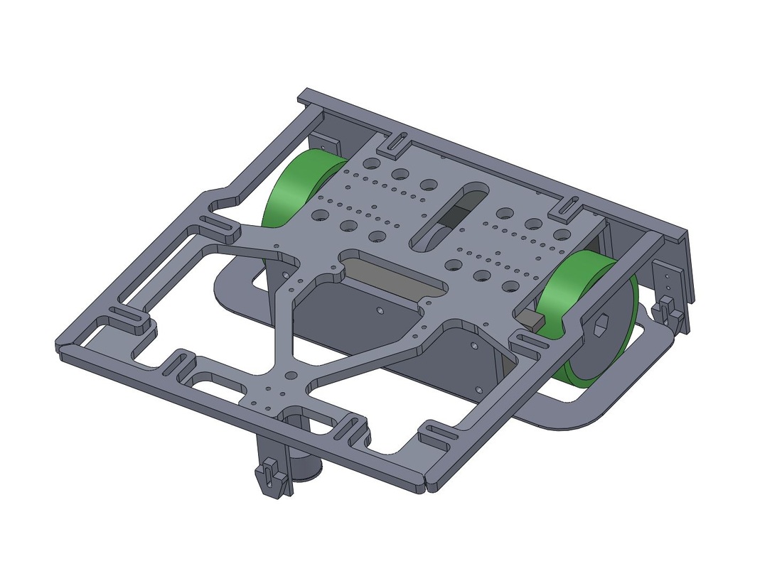
Now right side up, you can see the tapped holes and features in the Strong Back plate that allowed us to build up the upper levels of the vehicle.
You can also see in this view how the bumpers around the perimeter of the Strong Back are mounted using slotted holes. This ensured that we would be able to meet the dimensional constraints of the competitions without having to precisely measure the thickness of the foam, or track tolerance stack-ups during assembly.
The image below and to the left shows the bumpers installed. The image below and to the right shows the first level risers used for mounting the Arduino, power regulation board, and motor driver board.
|
|
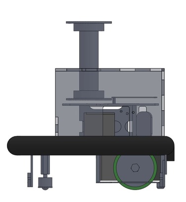
Upper Levels Designed For Access
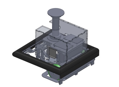
The upper levels of the bot were designed to enable easy integration of the electrical and sensor systems. The design also made them accessible for troubleshooting and iteration as we progressed with testing out the design. This was a great recommendation that was given to us early on by the teaching team and our coach, and it paid off huge for us as we progressed with our design.
A clear roll cage and a carbon fiber beacon tower were added after beating the brick to get us ready for the competition. The idea was to use light weight materials to keep our CG as low as possible.
The two images below show some additional views of the final vehicle assembly. The mechanical design is completely defined by the 3D CAD data provided, and is sufficient to reproduce this vehicle if desired.
|
|
Line Detector Height Placement
The mounting height of the line detectors (OPB704WZ reflective object sensor) affected its sensitivity greatly. We wanted to achieved maximum change in OPB704WZ output voltage when the robot crossed a line. This would limit the possibility of false readings from ambient light or diffused OPB704WZ LED light if placed too high.
To determine the optimal line detector height placement, sensitivity tests were performed at various heights from the ground. Output voltage readings were taken over both the black and white surfaces, and the difference in their readings was determined. From these tests, we determined the optimal line detector placement occurs at a height of 1/2" from the ground.
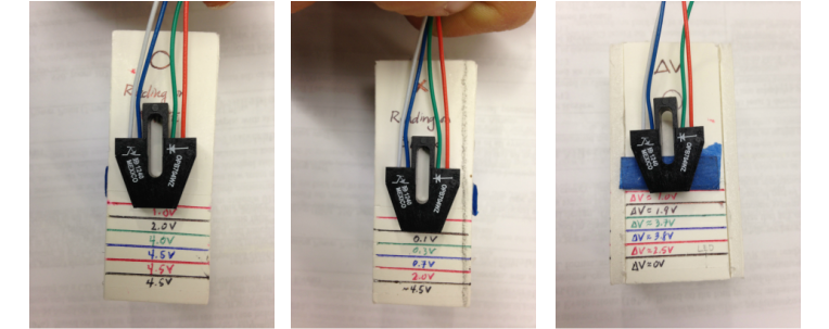
Left: Output voltage readings at heights differing by 1-1/8" detected by the OPB704WZ when placed over a white surface.
Center: Output voltage readings at heights differing by 1-1/8" detected by the OPB704WZ when placed over a black, non-reflective tape surface surface.
Right: The difference between OPB704WZ output voltage over a white and black surface.
Location of the line sensor on the robot was determined by the location of the supports between the robot and the playing field ground. One line sensor was place near each support: front left wheel, front right wheel, and castor. If any one of the three supports were to fall off the edge of the elevated field, we would be toast! Therefore, it was necessary to determine as quickly and closely as possible whether a support was near the black tape that constrained the playing area.
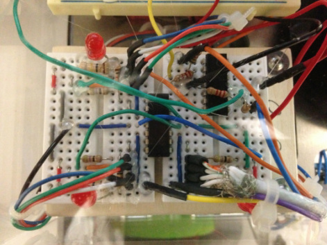
Due to limited availability of breadboards and time, we created the circuitry for all three line detectors by combining two smaller breadboards.
